

Transform Your Van Life
A DIY Engineer’s Guide to Off-Grid Power
As an electrical engineer with a background in avionics hardware and software, I’ve spent years designing systems that help commercial aircraft fly safely. So, when it came time to convert my camper van, I knew I wanted to build a robust, all-electric system. While I’m not a licensed house electrician, I understand the principles behind code requirements and feel right at home around electronics. This post walks through the decisions, layout, wiring, and lessons learned from building my van’s electrical system. Whether you’re planning your own build or just curious how it all works, I hope this helps demystify the process

🔧 System Overview: Key Specs & Components
Here are the major decisions I made when designing the system.
Specifications
Battery Capacity:
400 Amp Hour; Balanced capacity for cooking + hot water without overbuilding
Inverter Size:
3000 Watts; Supports two 15A appliances simultaneously (e.g., cooktop + water heater)
Solar Panel:
400 Watts; Largest that would fit on the roof, Upgraded for partial shade
Alertnator Charging:
Most reliable for daily charging while driving
Shore Power:
Added flexibility for charging at RV parks or at home
System Control:
CerboGX provides visual centralized monitoring and control
🧩 Core Components
I chose Victron Energy for most components. They’re widely used in the van life community and offer excellent integration. There are about eight core components in a camper van electrical system—everything else is wiring to connect them.
1
Battery Bank: Stores energy for off-grid use..
2
Inverter/Charger: Converts DC to AC and handles shore power input.
3
DC-DC Charger: Charges house batteries from the van’s alternator power, but only while driving.
4
Solar Panels: Harvest sunlight for passive charging.
5
Solar Charge Controller: Regulates solar input to protect batteries and charge them appropriately.
6
Shunt: Tracks current flow for accurate battery monitoring.
7
Cerbo GX: System brain—monitors, displays, and controls via touchscreen.
8
Fuse Box / Breaker Panel: Distributes and protects circuits.
🧩 Putting the System Together
Here is an overall schematic from Victron that shows a typical installation for an RV.: Dont;t worry, not all the parts shown are actually needed.

Wiring a camper van differs from wiring a house. Typically, homes use solid core wire: 14 AWG for 15-amp circuits and 12 AWG for 20-amp circuits, with larger wire sizes such as 12 AWG and 10 AWG reserved for devices like stoves, water heaters, dryers, or furnaces. Camper vans commonly use stranded wire due to its resistance to vibration and crimped connectors instead of direct connections.
Another distinction is that most systems in a camper van are powered directly by batteries. For example, only the water heater and AC plugs may operate on AC power, while appliances such as the refrigerator, water pump, fan, and lights run on 12V batteries. This setup conserves power because running an inverter uses extra energy; consequently, most devices have off switches to minimize power consumption when not in use.
Wiring of a 12V device also presents unique considerations compared to residential wiring. It is important to account for both current and wire length from the battery to the fuse box, and to each device. Copper wire is costly, so selecting the smallest safe gauge is standard practice. Larger gauge wires, often needed for 12V applications, usually require crimped connectors, which vary depending on the device. Separate wires are typically used for power and ground, following the convention of black for ground and red for positive.
To address these requirements, a company called Light Harvest Solar in Portland provided a kit containing most components necessary for assembly. Ordering parts individually online can lead to excess quantities.
The installation process involves organizing components in the intended area, considering space limitations, and minimizing wire runs. Planning is similar to assembling a puzzle, especially since large-gauge wires are generally inflexible. A box can be constructed using 80/20 aluminum framing and wood fiber board for sides and doors, with most components mounted vertically and batteries placed on a shelf above the wheel. Leaving the box open for airflow prevents overheating, especially for components with heat fins. After mounting devices, wires are cut to size, connectors are attached, and everything is connected.

For additional reference, EXPLORIST.life on YouTube offers detailed videos produced between 2020 and 2022, providing comprehensive guidance on camper van electrical systems.
☀️ Mounting the Solar Panel
Mounting the solar panel was easier than expected. Using DIYvan brackets, I attached them to the Ford Transit roof holes and ordered 80/20 cross beams; the panel fit neatly between them, resulting in a low-profile setup.

🧩 Wiring up the Van
Now that the van has a power system, the van needs to be wired to provide that power to the various devices in the van. The Light City Harvest kit provides the fuse box, but you’ll need to plan wire routes to each device, considering their locations and current requirements to select the right wire size. Some wires must run through the van’s frame, so pre-wiring before cabinetry installation is necessary. I installed the tall cabinet early to place the fuse block and then began pre-wiring as needed. Below is my wiring plan spreadsheet:
| Item | Location | Current | AWG | Switch | Type |
| Hot Water Heater | Galley | 15 | 12 | Control Panel Area | push Button Green |
| AC Outlet | Galley | 20 | 12 | GFI green | |
| AC Outlet | Galley Lower | 20 | 12 | Normal | |
| AC Outlet | Driver Wall | 15 | 12 | GFI green | |
| AC Outlet | Bed Access | 15 | 12 | Normal | |
| AC Outlet | Garage | 15 | 12 | Round | |
| Victron Control Panel | Control Panel | Special Cable | |||
| 12 Volt DC | Fuse | ||||
| Water Pump | Garage | 10 | 12 | Control Panel Area | push button red (10) |
| Fridge | Driver Middle | 15 | 12 | ||
| Ceiling Fan | Roof Back | 10 | 12 | ||
| Toilet Fan | Driver Middle | 7 | 16 | ||
| Heater | Driver Middle | 15 | 12 | ||
| weBoost | Cabinet | 5 | 16 | Control Panel Area | push button red (10) |
| Wifi Hot spot | Cabinet | 7 | 16 | Control Panel Area | push button red (10) |
| Bed adjuster | Bed Frame | 15 | 16 | Control Panel Area | Rocker (2) |
| Task Light Table | Driver Table | 16 | On Light | ||
| Task LightGalley | Roof Middle | 16 | On Light | ||
| Main Lighting | Roof | 12 | Counter | push button red | |
| Roof Light Bed | Roof | 16 | Control Panel Area | push button Red | |
| Roof Light Bed | Roof | 16 | Rear Wall | push button Red | |
| Night light | 16 | Control Panel Area | push button Red | ||
| USB Table | Driver Table | 10 | 12 | USB Quick charge | |
| USB Bed 1 | Head of Bed Left | 10 | 12 | ||
| USB Bed 2 | Head of Bed Right | 10 | 12 | ||
| Cigarette Socket | Garage | 10 | 12 | ||
| Outdoor Light side | Galley Lower | 16 | Counter | push button Red | |
| Outdoor light rear | Rear Roof | 18 | Cab | Rocker | |
| Airlift Control | Galley | 16 | Cab | Rocker |
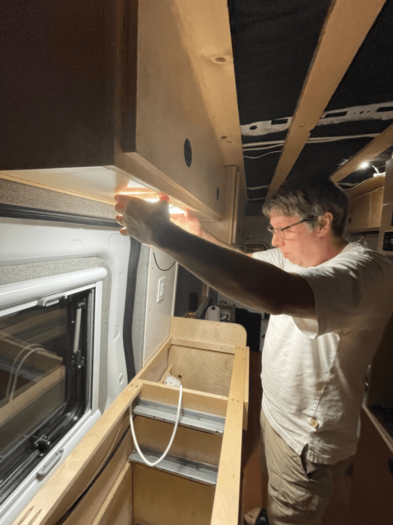
I installed illuminated switches using green for AC and red for 12V DC. This makes it easier to monitor power usage. A relay lockout system ensures the water heater only operates when the water pump is on. I also made custom switch panels using a metal print from Costco. This photo also shows off the touch screen dispaly from Victron.

☀️ Solar Panel Realities
Maybe the most disappointing aspect to the build was the solar panel output.
I chose a panel with shade-tolerant technology to avoid total power loss when partially shaded this is important for boondocking in forested areas. However, I underestimated how much angle and seasonal variation affect solar output, especially in the Pacific Northwest.
🔆 Seasonal Output Estimates (Flat-Mounted Panel in Seattle)
| Season | Sun Elevation @ Noon | Efficiency vs. Tilt | Estimated Pk Output |
| Summer | ~60–66° | ~85–95% | 340–380W |
| Spring/Fall | ~35–50° | ~60–75% | 240–300W |
| Winter | ~19–25° | ~30–50% | 120–200W |
Panels mounted flat are never perpendicular to the sun, especially in winter—so actual output is always less than the rated wattage.
Still, it’s worth having. Even partial charging during the day helps offset usage, especially when boondocking.
Verdict: What I would do differently
There’s little I would change. The system works well overall, and 400 amp/hr battery capacity has been sufficient; I might consider 600 amp/hr if smaller batteries were available. While the Cerbo GX display is pricey, I find its monitoring features valuable. The only modification I have made to the electronics since building the vas was to add a fuse between the vehicle battery and the Victron DC-DC charger for easier resets. The solar panel hasn’t provided as much charge as expected during boondocking, but it still helps supplement battery power. Therefore, if I were to build another van I would use a solar panel again especially for boondocking.
- Battery Capacity: 400Ah has worked well. If batteries were smaller, I’d consider 600Ah.
- Cerbo GX Display: Optional but worth it for visual monitoring and inverter control.
- DC-DC Charger Fuse: Added an accessible fuse after needing to reset the unit—lesson learned.
- Solar Panel: Underwhelming in shaded areas, but still useful for daytime trickle charging.
📚 Resources
- LightHarvest Solar – Portland-based supplier that helped design my kit.
- EXPLORIST.life (YouTube) – Best resource for DIY camper van electrical wiring (2020–2022 videos especially).
- DIYvan – Great source for Transit-compatible mounting brackets.

Thinking about your own van build?
Drop us an email – we’re happy to share what worked (and what didn’t).